20454363-4
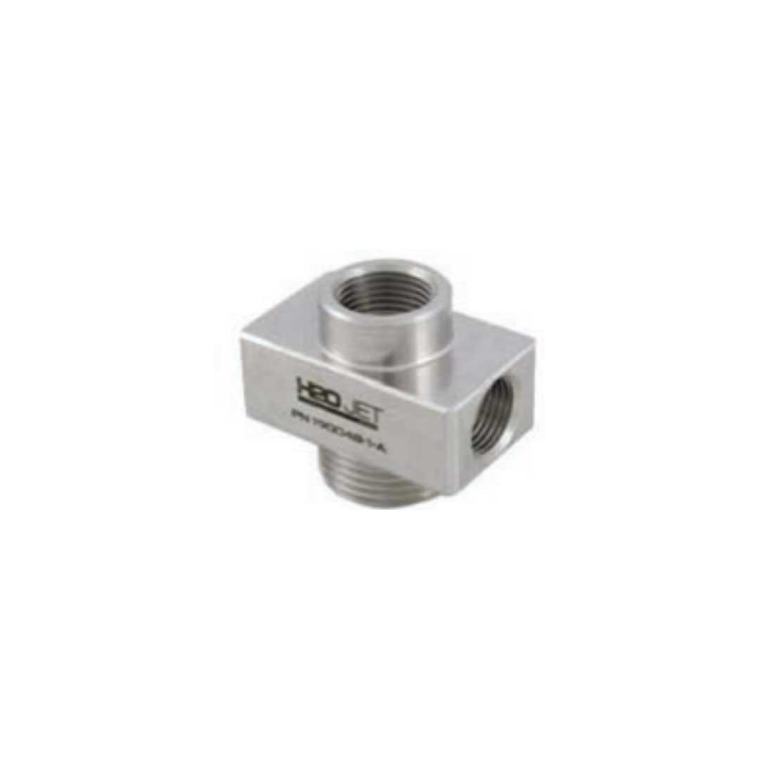
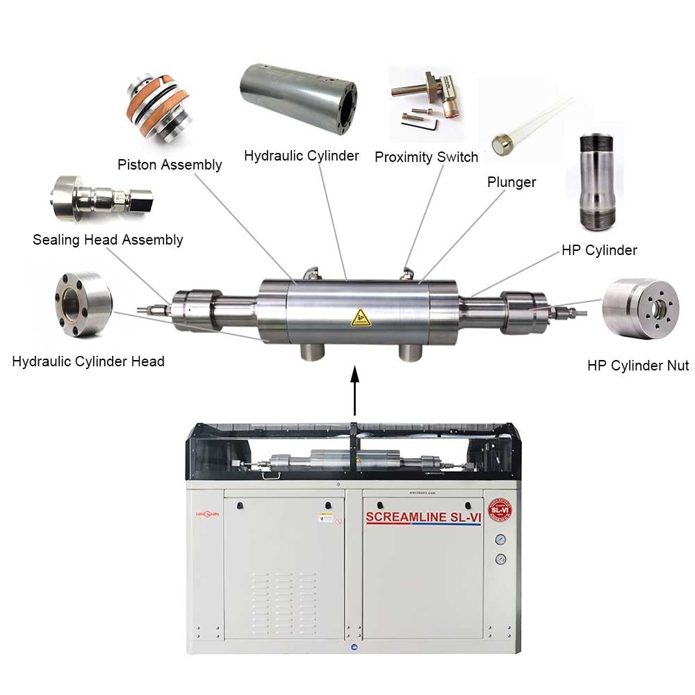
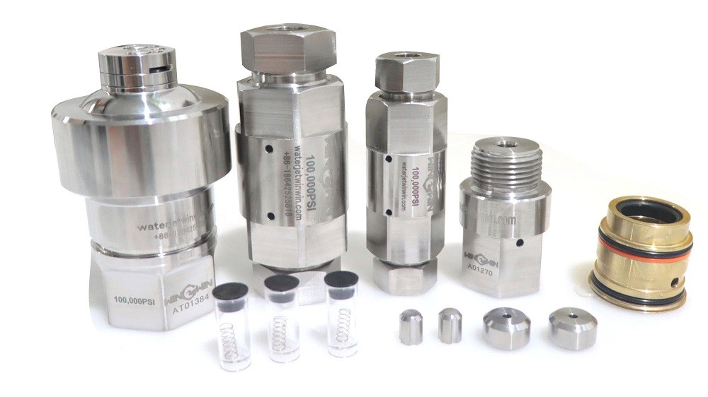
Product ID: 20454363-4 – High-Pressure Check Valve Assembly
Description:
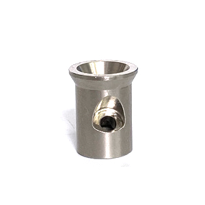
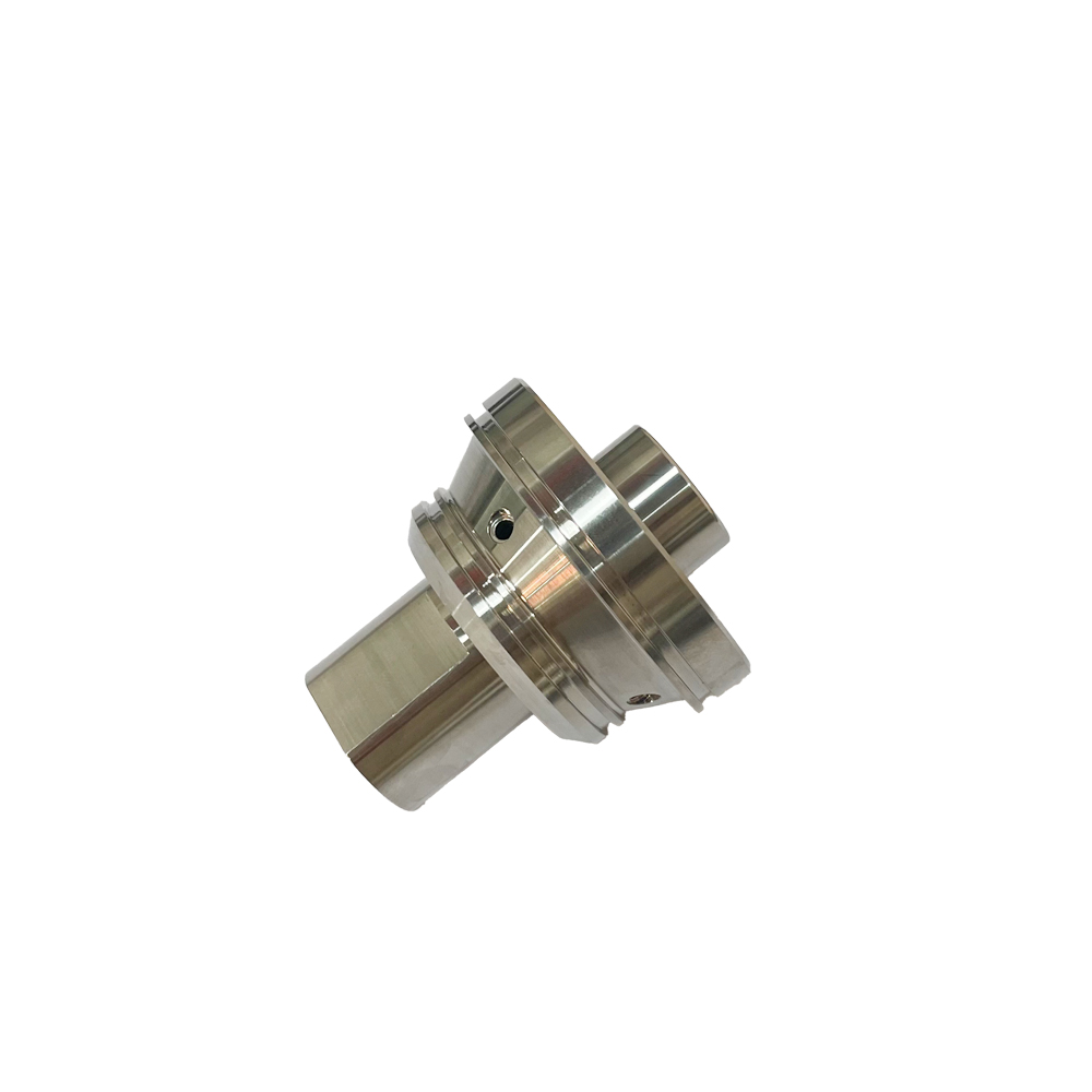
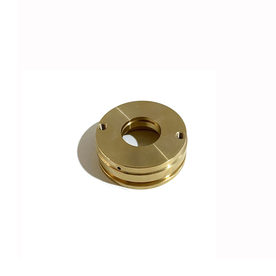
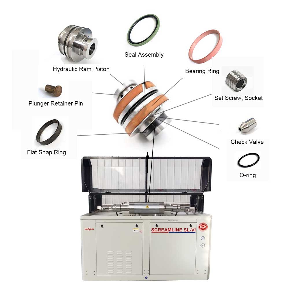
This component is a high-pressure check valve assembly designed for waterjet cutting systems. It is a one-way flow control device that allows high-pressure water or abrasive slurry to flow in only one direction, preventing reverse flow back into the intensifier pump or upstream components. The “-4” suffix may indicate a specific port size, pressure rating, or design revision.
Applications:
Used in waterjet cutting machines to direct pressurized water from the intensifier toward the cutting head while preventing backflow.
Installed on the outlet side of the intensifier pump or between multiple intensifier cylinders to maintain unidirectional flow.
Suitable for both pure water and abrasive waterjet systems requiring reliable reverse flow prevention under ultra-high pressure.
Features:
Constructed from high-strength, corrosion-resistant stainless steel or hardened alloy to withstand extreme pressure and erosion.
Designed for ultra-high pressure operation, typically rated at 60,000 psi (approximately 4,137 bar) or higher.
Contains a precision-machined valve seat and a poppet, ball, or plunger type sealing element.
Spring-loaded or gravity-actuated design ensures rapid seating when forward flow ceases or reverse pressure occurs.
Includes anti-extrusion backup rings and high-pressure seals to prevent leakage around the valve internals.
Precision-ground sealing surfaces provide leak-tight shut-off under reverse pressure conditions.
Engineered for minimal pressure drop during forward flow to maintain cutting efficiency.
Compact design allows installation in tight spaces within the high-pressure plumbing system.
Maintenance:
Fully depressurize the waterjet system and disconnect power before servicing the check valve assembly.
Remove the valve from the high-pressure line, noting the flow direction indicated on the valve body.
Disassemble the valve according to the equipment service manual, carefully retaining all internal components.
Inspect the valve seat for wear, pitting, erosion, cracking, or indentation caused by repeated sealing impact.
Inspect the poppet, ball, or plunger sealing surface for similar damage or deformation.
Check the spring (if present) for fatigue, breakage, or loss of tension.
Examine all seals, O-rings, and backup rings for wear, extrusion, or chemical degradation.
Inspect the valve body interior for cracks, corrosion, or erosion from high-velocity fluid flow.
Clean all metal components using a soft cloth and low-pressure water or compatible solvent; avoid abrasive tools.
Replace any worn or damaged components, including seals, spring, or sealing element.
During reassembly, lubricate seals and moving parts with manufacturer-recommended high-pressure grease.
Ensure the valve components are assembled in the correct orientation and sequence as shown in the service manual.
Tighten threaded connections to the torque values specified by the equipment manufacturer.
After reinstallation, slowly pressurize the system and verify forward flow functionality.
Test reverse flow prevention by observing the pressure gauge for pressure decay when upstream pressure is released.
Replace the entire check valve assembly if the valve body or seat is damaged beyond repair.