05131503-Hydraulic-Hose-Assembly-75.1241.3-1
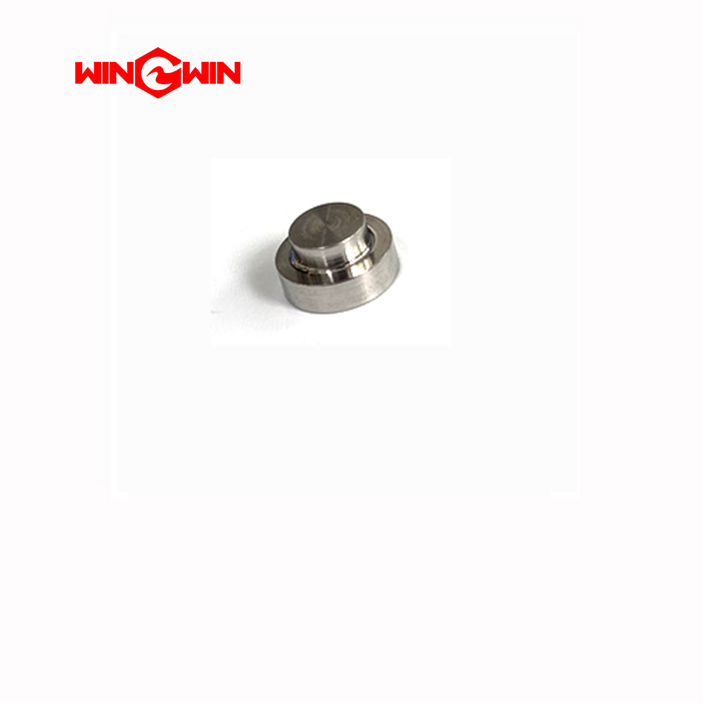
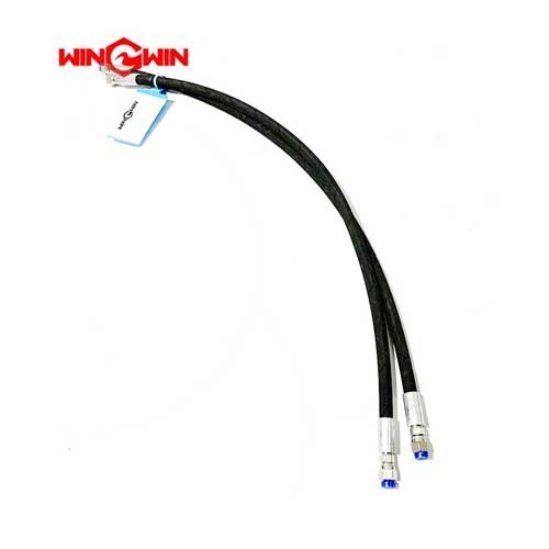
Product Name: Hydraulic Hose Assembly (.75 x 38.0) – Part No. 05131503
Description:
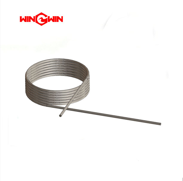
This component is a hydraulic hose assembly, specifically a .75 inch (3/4″) inner diameter hose with a length of 38.0 inches. It is designed for use in the hydraulic circuit of waterjet cutting systems, serving as a flexible conduit to transmit hydraulic fluid under pressure between system components.
The hose assembly is manufactured with a synthetic rubber inner tube, textile or steel wire reinforcement for strength, and a durable rubber outer cover resistant to abrasion and hydraulic fluids. It is supplied as a complete assembly with pre-crimped, corrosion-resistant steel fittings on both ends, ready for installation.
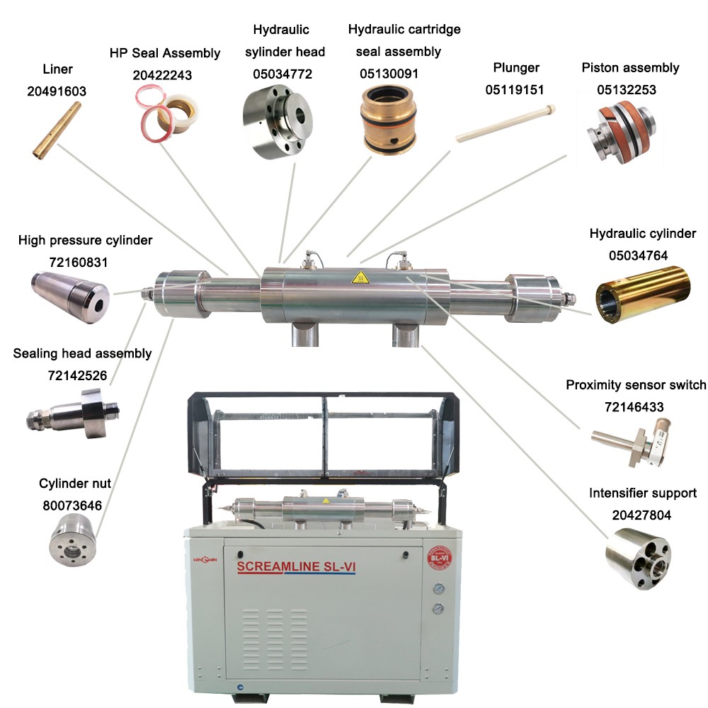
According to the official parts diagram for the Oil/Air Heat Exchanger Kit (Assembly 72163210), this hose assembly is listed as Item 3 with a quantity of 1 required per assembly. It plays a critical role in the thermal management of the hydraulic system, transporting hot hydraulic oil to the heat exchanger for cooling before returning it to the reservoir.
Applications:
Transmits hydraulic fluid between the intensifier pump, hydraulic manifold, heat exchanger, and reservoir in waterjet cutting systems
Specifically used in the Oil/Air Heat Exchanger Kit (Assembly 72163210) for hydraulic temperature regulation
Serves as a flexible connector for high-pressure hydraulic lines, accommodating machine motion and dampening vibration
Suitable for hydraulic circuits operating at system pressures up to 60,000-94,000 PSI (approximately 4,137-6,480 bar)
Features:
Hydraulic Hose Construction: Features a synthetic rubber inner tube, steel wire braid or spiral reinforcement, and a durable rubber outer cover resistant to abrasion, oil, and hydraulic fluids
Size Designation: .75 indicates a 3/4 inch nominal inner diameter, a standard size for medium-flow hydraulic circuits in waterjet systems
Length: 38.0 inches, providing sufficient length for proper routing within the hydraulic power unit
Pre-assembled: Supplied as a complete hose assembly with pre-crimped fittings, ready for installation
Temperature Range: Designed for safe operation within the temperature limits of the hydraulic fluid and environment (typically -40°C to +100°C for NBR rubber)
Working Pressure: Engineered for the specific pressure requirements of waterjet intensifier systems
Maintenance:
Failure Diagnosis (When to Replace):
External Leakage: Visible hydraulic oil weeping from the hose cover or fittings indicates failure; a leaking assembly must be put out of operation immediately
Cover Damage: Inspect for cuts, abrasion, bulging, blistering, kinking, or exposed wire reinforcement; hoses with exposed reinforcement must be withdrawn from service
Fitting Condition: Check for cracked, corroded, or damaged fittings; deformed or leaking fittings warrant immediate replacement
Deformation: Separation of layers, blistered, crushed, or kinked hose indicates internal failure
Hardening or Cracking: If the hose feels unusually stiff or shows heat cracks, replace it immediately
Visual Inspection: Replace immediately if any visible damage is detected during daily visual inspections
Installation and Maintenance Guidelines:
Pre-Installation Inspection: Before installation, verify that the hose cover shows no damage, fittings show no corrosion, and threads/sealing faces are clean and undamaged
Avoid Hose Twisting (Critical): When installing, ensure the hose is not twisted. Use the brand line on the hose as a straight reference to verify correct orientation. Pressure applied to a twisted hose can shorten its life or loosen connections
Minimum Bend Radius Compliance: Do not bend the hose to less than its minimum bend radius; ensure sufficient straight length (at least 1.5 times the hose outer diameter) between the fitting and the start of any bend
Secure Routing: Route the hose to avoid sharp edges, hot surfaces, or moving parts. Use clamps or ties to secure and prevent chafing. Ensure the routing allows for relative movement without pulling or straining the connections
Two-Wrench Method: Use two wrenches—one to hold the fitting and one to tighten the nut—to prevent twisting the hose during installation
Torque Compliance: When installing, tighten the end fittings to the specific torque value listed in the equipment service manual using a calibrated torque wrench
Full Depressurization (Critical): Before any maintenance, fully depressurize the hydraulic system, shut down the high-pressure water pump, and follow lockout/tagout procedures
Relieve Residual Pressure: Even after system shutdown, trapped pressure may remain. Be cautious when loosening fittings. Never attempt to locate a hydraulic leak by "feeling" with hands; high-pressure fluid can penetrate skin and cause severe injury
Storage: Store spare hose assemblies in a cool, dry, dark place with ends capped. Ideal storage temperature is +10°C to +20°C; do not exceed 38°C. Keep away from ozone, UV light, oils, solvents, and corrosive substances
Repair Policy: Repair of hose assemblies is not recommended; if a hose is damaged, replace the entire assembly. Do not reuse hose that has been in service for other applications