05137724-3-Way2-Pressure-Valve-38-High-Pressure-Fitting-and-Valve-Assemblies.920.3-1
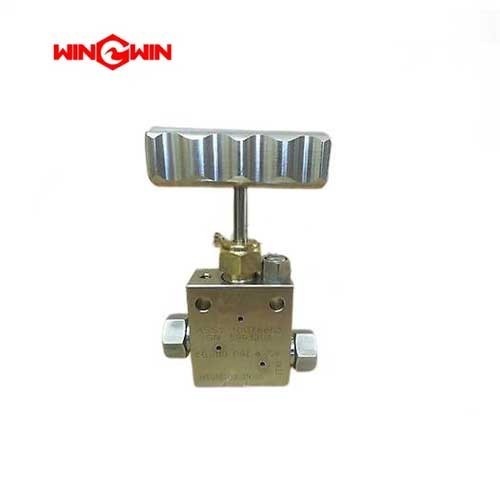
Product Name: 3-Way/2-Pressure Valve (3/8″ High-Pressure) – Part No. 05137724
Description:
The 05137724 is a 3-way (three-port), 2-pressure high-pressure valve assembly specifically designed for 3/8″ high-pressure waterjet plumbing systems . This component is engineered to manage and route the flow of high-pressure water (up to 60,000 psi / 4,137 bar) through multiple pathways, providing operators with greater control over fluid distribution . It is part of the High-Pressure Fitting and Valve Assemblies product family and is specifically listed as a 3 Way/2 Pressure Valve for use in demanding waterjet cutting equipment . The “.38” in its designation refers to the standard 3/8-inch tube outer diameter (OD) connection size, making it compatible with standard 3/8″ high-pressure fittings and tubing.
Applications:
Flow Distribution & Diversion: Used to direct or split the high-pressure water stream from the intensifier pump to different outputs (e.g., directing flow to a secondary cutting head or bypass line) .
Pressure Switching: Provides a “2‑pressure” function, allowing the system to switch between two distinct pressure settings (e.g., switching between a high cutting pressure and a lower piercing pressure) without requiring a complete pump recalibration.
System Control: Installed in the high-pressure manifold or near the cutting head to enable advanced fluid control strategies, such as purging lines or isolating components for maintenance.
Features:
3‑Port/2‑Pressure Configuration: The integrated design reduces potential leak points by combining multiple valve functions into a single, compact body .
3/8″ HP Compatibility: Designed specifically for 3/8″ outer diameter high-pressure tubing, a standard size for medium to high flow waterjet circuits .
Heavy‑Duty Construction: Manufactured from corrosion-resistant, high-strength stainless steel or alloy to withstand the extreme pressure cycles and erosive environment of waterjet operation .
Safety Integration: Often used in conjunction with pressure relief devices and other safety features to prevent over‑pressurization .
Maintenance:
Inspection & Troubleshooting:
External Leakage: Check all three ports for signs of water weepage. A leak indicates seal failure or a damaged valve seat.
Pressure Fluctuations: If the system fails to switch between the two pressure levels properly, the internal spool or seals may be worn.
Performance Drop: Erosion or blockage in the internal passages can cause a pressure drop or reduced flow.
Replacement & Handling:
Full Depressurization (Critical): Always lock out the main electrical disconnect, bleed down all high‑pressure water and hydraulic lines, and follow lockout/tagout procedures before any valve maintenance .
Inspect Seats & Seals: During overhaul, disassemble the valve body and inspect the seats, sealing surfaces, and O‑rings for pitting, nicks, or deformation.
Use Proper Tools: Always use two appropriately sized wrenches to avoid twisting the valve body when disconnecting fittings.
Torque Compliance: Tighten the valve’s gland nuts and fittings to the manufacturer’s specified torque values.
Lubrication: Apply high‑pressure anti‑seize lubricant to the threads during reassembly to prevent galling.
Replacement: Due to the precision fit of the internal components, it is generally recommended to replace the valve as a complete assembly if internal damage is found, rather than attempting to repair it in the field .