05127854-Proximity-Switch
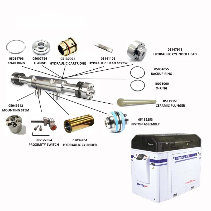
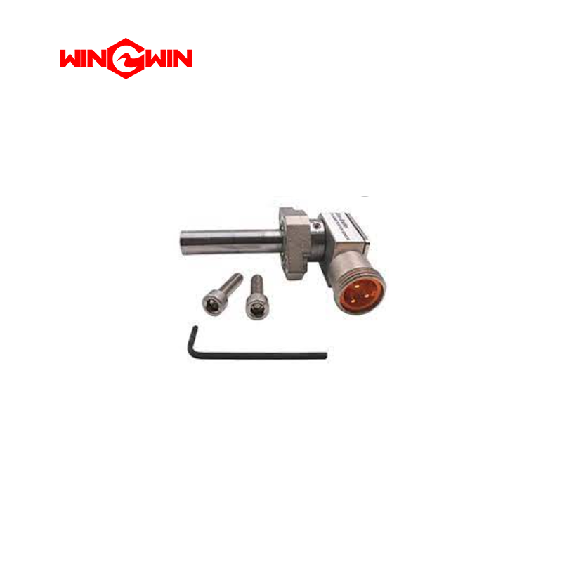
Product ID: 05127854 – Proximity Switch (Position Sensor for Intensifier Pump)
Description:
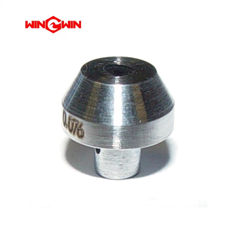
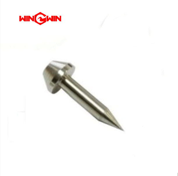
This component is a proximity switch, also known as a non-contact position sensor or inductive sensor, designed for high-pressure waterjet intensifier pumps . It is an electronic sensing device that detects the presence or absence of a metallic target without physical contact. This switch is used to monitor the position of moving components such as the intensifier piston or plunger assembly, providing feedback to the pump controller for proper sequencing and stroke reversal. This specific sensor is designed for use on intensifier pumps rated for ultra-high pressure operation .
Applications:
Used in waterjet intensifier pumps to sense the end-of-stroke position of the reciprocating piston or plunger assembly.
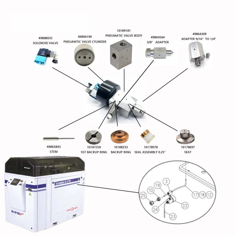
Installed on the hydraulic cylinder or pump frame, positioned to detect the piston or a target magnet as it approaches the end of its travel.
Suitable for ultra-high pressure waterjet systems rated for high-pressure operation, compatible with intensifier pumps requiring precise stroke timing for optimal performance and efficiency .
Features:
Non-contact inductive sensing eliminates mechanical wear and increases service life compared to mechanical limit switches.
Constructed with a rugged, sealed housing rated for water resistance and protection against abrasive dust and hydraulic fluid exposure.
Designed to detect ferrous metal targets through a specified air gap.
Pre-wired with an integral cable or equipped with a connector for electrical integration with the pump control system.
LED indicator on the sensor body provides visual confirmation of target detection and power status for easy troubleshooting.
Engineered to withstand vibration, temperature fluctuations, and wet operating conditions typical of waterjet pump environments.
Includes mounting hardware (typically two M6 x 22mm screws) for secure attachment to the pump frame or cylinder assembly .
Maintenance:
Regular Inspection: Periodically inspect the sensor face for buildup of metallic debris, abrasive dust, or hydraulic fluid that could reduce sensing range or cause false triggering.
Cleaning: Clean the sensor face with a soft cloth and mild solvent if necessary; do not use abrasive tools that could scratch the sensing surface.
Cable Check: Inspect the sensor cable or connector for cuts, abrasion, moisture ingress, corrosion, or loose connections; repair or replace as needed.
Air Gap Verification: Verify correct air gap between the sensor face and the target as specified in the equipment manual; incorrect gap may cause missed or false triggering.
Functional Testing: Test sensor operation by manually moving the target (or simulating piston movement) into and out of the sensing zone while observing the LED indicator or monitoring the control system signal.
Replacement Criteria: Replace the proximity switch if the LED fails to illuminate when the target is present, if the output signal remains stuck in one state, if the sensor housing is cracked or damaged, or if the cable is damaged beyond repair.
Full Depressurization: Before replacing the sensor, fully depressurize the waterjet system, disconnect electrical power, and follow lockout/tagout procedures.
Proper Sealing: When installing a replacement, ensure the sensor is properly seated and any sealing washers or O-rings are in good condition to prevent moisture ingress.
Cable Routing: Route the cable away from sharp edges, moving parts, hydraulic hoses, and high-temperature surfaces; use cable ties to secure wiring and prevent strain on the sensor connection.
Cross-Reference Note: This component may be referenced under alternative part numbers such as 20453934, 05127584, or 10180081 depending on system configuration . Verify compatibility before installation.