05139506-Water-Jet-Cutting-Pump-Pressure-Gauge-0-200-psi.856.3-1
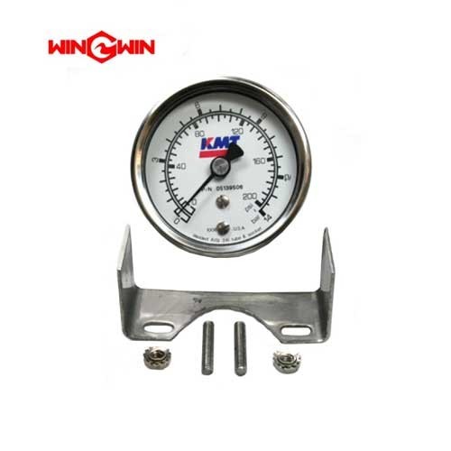
Product Name: Pressure Gauge, 0-200 psi (Low-Pressure Water Supply) – Part No. 05139506
Description:
This component is a 0-200 psi analog pressure gauge specifically designed for monitoring the low-pressure water supply line in waterjet cutting systems. As a critical diagnostic and safety instrument, it provides a continuous visual indication of the inlet water pressure being supplied to the intensifier pump before it is pressurized to cutting levels (typically 60,000+ psi).
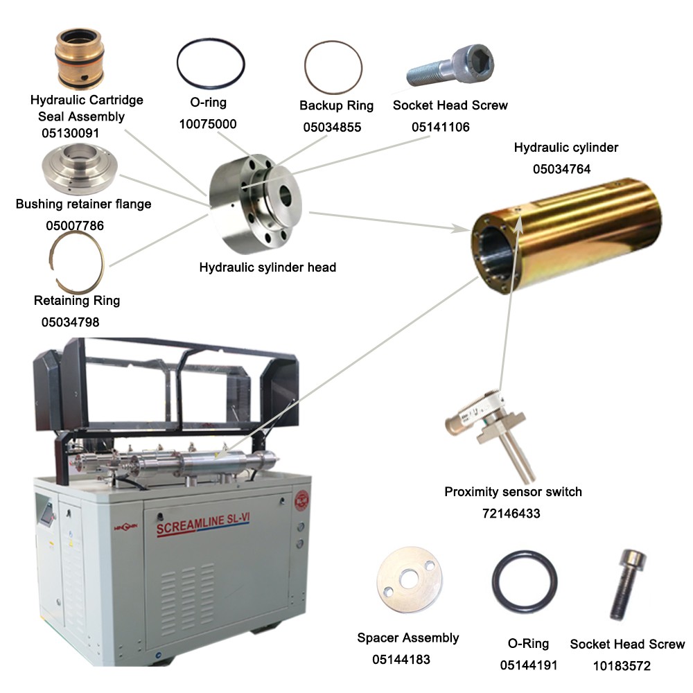
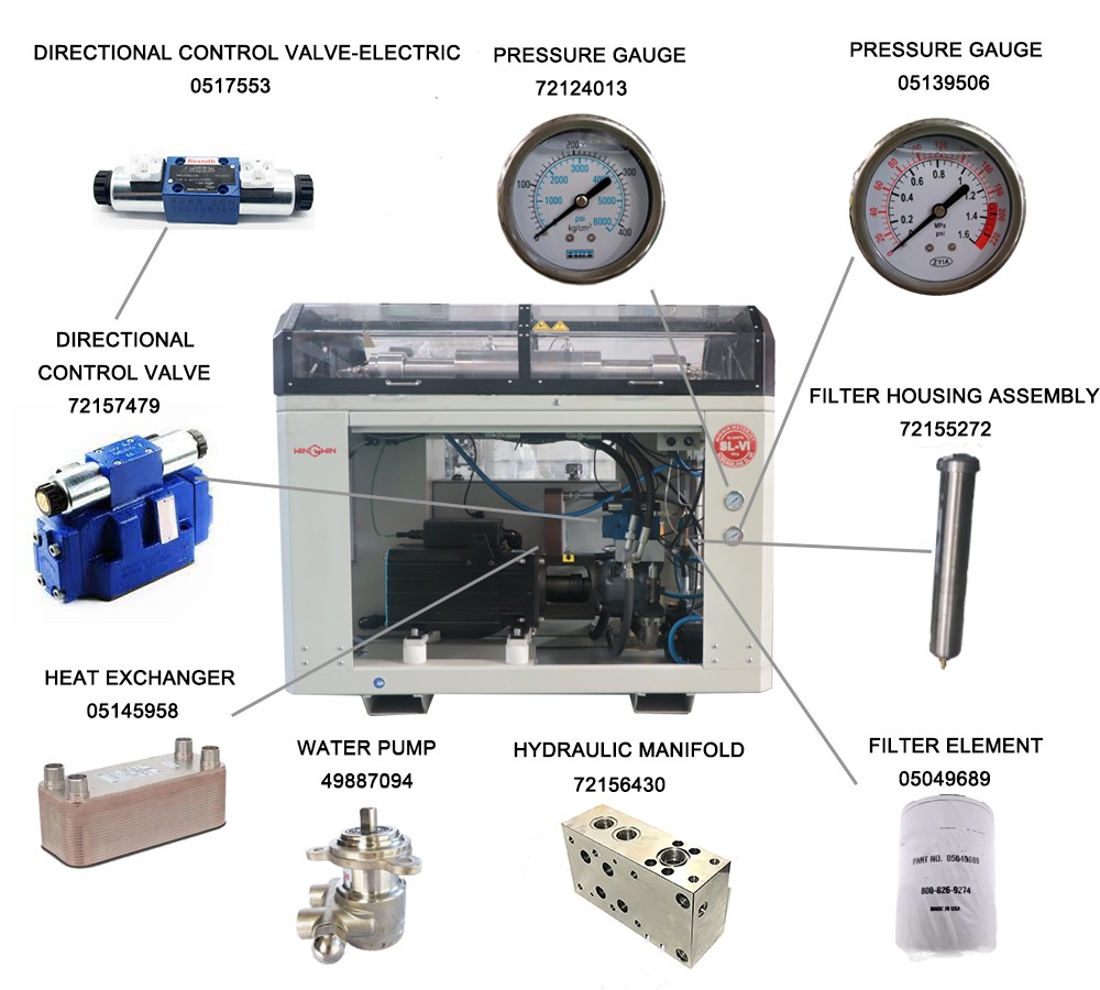
It is a standard OEM part used primarily in the low-pressure water filter assembly and bulkhead piping systems. The gauge typically features a 1/4" NPT (National Pipe Thread) connection with a lower mount configuration, a durable ABS or steel case, and a clear acrylic lens. The 0-200 psi range is specifically chosen because the acceptable water supply pressure for most intensifier pumps is between 40 psi and 125 psi. This gauge is listed as Item 1 in the Bulkhead Pipe Assembly (P/N 72152927) and is used in various waterjet cutting systems.
Applications:
Mounted on the low-pressure water filter assembly or bulkhead to display the incoming water pressure from the facility supply.
Provides essential real-time data for the operator to verify that the water supply pressure is within the acceptable range (typically 40-110 psi) before the intensifier starts.
Used as a primary diagnostic tool during troubleshooting to identify issues such as clogged filters, closed supply valves, or inadequate facility water pressure.
Essential for protecting the intensifier pump from cavitation (damage caused by insufficient water flow).
Features:
Pressure Range: 0 to 200 psi (pounds per square inch).
Primary Scale: Typically displays pressure in psi, with a secondary scale in bar or kPa depending on the model.
Connection: 1/4" NPT male connection, standard for low-pressure water circuits.
Construction: Wetted parts (components in contact with water) are typically made of brass or copper alloy to resist corrosion.
Dial Size: Common dial sizes range from 1.5" to 2.5" in diameter for easy readability in industrial environments.
Accuracy: Standard industrial grade (e.g., ASME B40.1 Grade B, ±3/2/3% of span).
Case Material: Black ABS plastic or painted steel for durability in workshop environments.
Critical Monitoring Role: The gauge allows the operator to monitor the differential pressure between the pre-filter and post-filter. A significant difference (>10 psi) indicates a clogged filter element requiring replacement.
Maintenance:
Failure Diagnosis (When to Replace):
Inaccurate Reading / Zero Offset: If the gauge does not return to zero when the pump is off and the water supply is depressurized, it is faulty and must be replaced.
Fluctuating or Sticking Needle: A needle that jumps erratically or sticks at a certain pressure indicates internal mechanical damage.
Fogging or Water Inside the Lens: Moisture inside the gauge indicates seal failure and will lead to inaccurate readings.
External Water Leakage: Water leaking from the back of the gauge or the fitting connection requires immediate replacement.
Cracked Lens or Case: Physical damage compromises safety and readability.
Inconsistent with System Behavior: If cutting performance is poor (e.g., slow traverse speeds) but the gauge reads normal pressure, the gauge may be faulty.
Inspection and Replacement Guidelines:
Daily Visual Check: Incorporate the gauge into daily start-up procedures. Verify the pressure reading is consistent with the facility's water supply (typically above 40 psi and below 110 psi).
Filter Change Indicator: Monitor the gauge during pump operation. If the pressure reading drops significantly (e.g., below 40 psi) or if the pressure differential between gauges before and after a filter exceeds 10 psi, replace the filter element immediately.
Bulkhead Assembly Installation: When replacing the gauge in a bulkhead assembly, apply a small amount of thread sealant (e.g., PTFE tape) to the male threads of the new gauge to prevent water leaks. Do not overtighten, as this can damage the gauge casing or the bulkhead fitting.
Torque (Hand Tighten): Tighten the gauge snugly by hand plus approximately 1/2 to 3/4 of a turn with a wrench. Use a wrench on the gauge's hex fitting, not on the round case.
Full Depressurization (Critical): Before removing or installing the gauge, fully depressurize the waterjet system, shut off the water supply, and follow lockout/tagout procedures.
Check for Restrictions: If the gauge reads low, do not immediately replace the gauge. First, verify the water supply valve is fully open, check the inlet strainer for clogs, and ensure hoses are not kinked.
Cross-Reference Information:
OEM Part Number: 05139506
Assembly Location: Item 1 in Bulkhead Pipe Assembly (P/N 72152927)
Connection: 1/4" NPT (Lower Mount)
Pressure Range: 0-200 psi
Application: Low-Pressure Water Supply Monitoring