20468732 heat exchanger
Product ID: 20468732 – Heat Exchanger / Hydraulic Oil Cooler
Description:
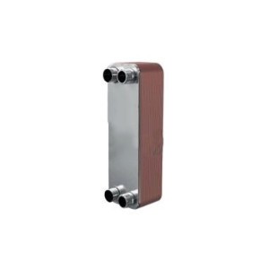
This component is a heat exchanger, also known as a hydraulic oil cooler or cooling system radiator, designed for high-pressure waterjet cutting systems. It is a critical component of the cooling system that removes excess heat generated by the hydraulic pump, intensifier assembly, and hydraulic oil during continuous operation. The heat exchanger dissipates thermal energy from the hydraulic fluid, maintaining optimal operating temperatures and preventing overheating-induced component failure.
The heat exchanger typically consists of a series of finned tubes or plate-type cooling elements through which hydraulic oil flows, while either air or water passes over the cooling surfaces to absorb and carry away heat. The construction materials include corrosion-resistant metals such as copper, aluminum, or stainless steel to withstand continuous exposure to hot hydraulic fluids and ambient moisture in waterjet operating environments.
Applications:
Used in waterjet cutting machines to cool hydraulic oil circulating through the intensifier pump and hydraulic power unit
Installed in the hydraulic oil return line between the intensifier outlet and the reservoir tank, or integrated into the hydraulic power unit assembly
Suitable for high-pressure hydraulic systems in waterjet intensifier pumps operating at hydraulic pressures of 1,500–5,000 PSI (approximately 100–345 bar) with oil flow rates up to 30–60 L/min depending on configuration
Compatible with SL-V, SL-VI, Classic series, OEM intensifier assemblies, and robotic waterjet cutting stations
Features:
Thermal Dissipation Capacity: Engineered to handle heat loads of 10–50 kW depending on hydraulic system size, maintaining oil temperature within the optimal range of 40–60°C (104–140°F)
Fin or Plate Design: Features high-density fin or plate-type cooling elements that maximize heat transfer surface area while maintaining compact dimensions
Corrosion-Resistant Construction: Manufactured from copper-brass alloys, aluminum, or stainless steel with anti-corrosion coatings to resist degradation from water and hydraulic fluid exposure
Electric or Hydraulic Fan Drive: Equipped with an electric fan motor (typically 24V DC or 110V AC) or hydraulic motor-driven fan for forced air cooling
Thermostatic Control: May include integrated thermostatic bypass valve that directs oil flow through the cooler only when temperature exceeds set point (typically 45–55°C / 113–131°F)
Bypass Protection: Internal spring-loaded bypass valve opens at high differential pressure (typically 3–5 bar / 45–75 PSI) to prevent cooler rupture during cold starts or oil viscosity spikes
Filtration Integration: Often combined with return line filter assembly, allowing combined cooling and filtration in a single component
Maintenance:
Regular Cleaning (Critical): Clean the heat exchanger fins or cooling surfaces regularly to remove accumulated dust, abrasive particles, and debris. Restricted airflow is the most common cause of overheating. Use compressed air or low-pressure water spray from the inside outward; avoid damaging delicate fins
Inspection: Visually inspect the heat exchanger for signs of oil leakage at fittings, corrosion, fin damage, or physical obstruction. Pay particular attention to areas where the unit mounts to the machine frame
Temperature Monitoring: Monitor hydraulic oil temperature during operation. If temperatures consistently exceed 55–60°C (131–140°F), inspect the cooler for blockage, fan operation failure, or inadequate airflow
Fan Motor Check: Periodically verify that the cooling fan operates when the hydraulic system reaches operating temperature. Listen for unusual noises (grinding, rattling) indicating bearing failure
Fluid Level Verification: Ensure hydraulic oil level in the reservoir is correct; low oil levels reduce heat dissipation capacity and may cause air entrainment
Pressure Drop Measurement: If equipped with pressure gauges before and after the cooler, monitor pressure drop. Excessive drop (typically > 3–5 bar / 45–75 PSI) indicates internal blockage requiring cooler replacement
Connection Inspection: Check all hydraulic fittings for leaks; tighten to torque specifications in the equipment service manual
Full Depressurization: Before servicing the heat exchanger, fully depressurize the hydraulic system (shut off pump, cycle intensifier to bleed stored pressure), shut off the high-pressure water system, disconnect electrical power to the fan, and follow lockout/tagout procedures
Replacement Criteria: Replace the heat exchanger if any of the following are detected:
External hydraulic oil leakage from cooler body (indicates tube or seal failure)
Internal blockage causing excessive pressure drop that cleaning cannot resolve
Severely damaged or corroded cooling fins affecting heat transfer
Fan motor failure (replace motor separately if available, or entire cooler assembly)
Repeated overheating despite clean fins and functioning fan
Environmental Disposal: Dispose of old heat exchangers and recovered hydraulic oil in accordance with local environmental regulations
Cross-Reference Information: This component may be listed as item 2 in cooling system or hydraulic power unit parts diagrams; verify cooler dimensions, port sizes (typically SAE or NPT threads), and heat load rating before replacement