10079580-4
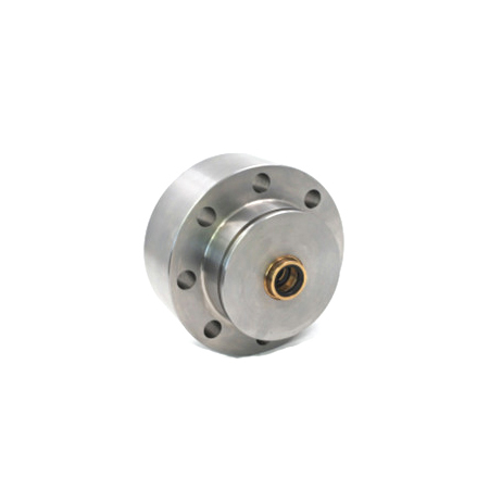
Product ID: 10079580-4 – Dump Valve / Relief Valve Assembly
Description:
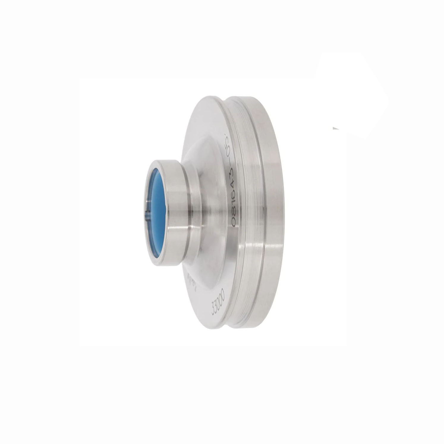
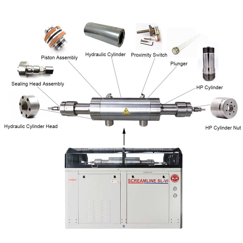
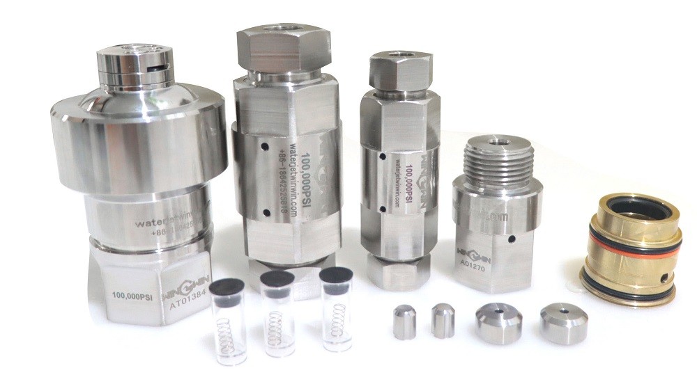
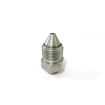
This component is a dump valve or relief valve assembly designed for waterjet cutting systems. It is a high-pressure control valve that rapidly diverts or releases pressurized water from the system to stop the cutting jet instantly. The “-4” suffix may indicate a specific version, port size, or pressure rating.
Applications:
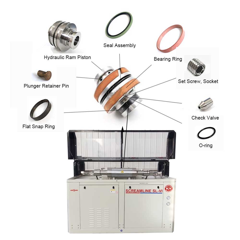
Used in waterjet cutting machines to stop the cutting jet rapidly during program pauses, tool changes, or emergency stops.
Installed between the high-pressure pump or intensifier and the cutting head to provide on/off jet control.
Suitable for both pure water and abrasive waterjet systems requiring fast, reliable pressure dump functionality.
Features:
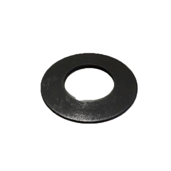
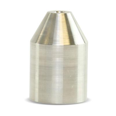
Constructed from high-strength, corrosion-resistant stainless steel or hardened alloy to withstand repeated pressure cycling.
Designed for ultra-high pressure operation, typically rated at 60,000 psi (approximately 4,137 bar) or higher.
Provides rapid actuation response, typically within milliseconds, for precise jet start/stop control.
Includes precision-machined internal sealing surfaces and wear-resistant valve seats.
May be pilot-operated or directly actuated depending on the specific system design.
Engineered to vent high-pressure water safely to drain or tank when the valve opens.
Maintenance:
Fully depressurize the waterjet system and disconnect power before servicing the dump valve assembly.
Remove the valve from the system carefully, noting the orientation of inlet and outlet ports.
Disassemble the valve according to the equipment service manual, taking care not to damage internal sealing surfaces.
Inspect the valve seat and poppet or plunger for wear, erosion, cracking, or pitting caused by high-velocity water flow.
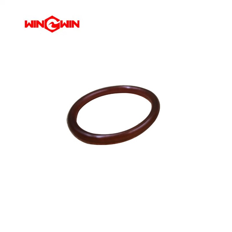
Check all seals, O-rings, and backup rings for wear, extrusion, or chemical degradation.
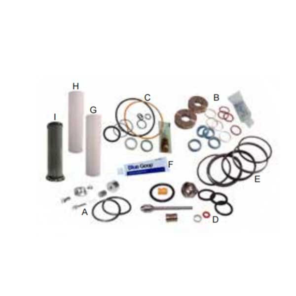
Replace any worn or damaged components with parts specifically designed for this valve assembly.
Clean all metal components using a soft cloth and low-pressure water or compatible solvent; avoid abrasive tools.
Inspect the valve body for cracks, corrosion, or thread damage.
During reassembly, lubricate seals with manufacturer-recommended high-pressure grease.
Tighten all threaded connections to the torque values specified in the service manual.
After reinstallation, slowly pressurize the system and test the dump valve function repeatedly to ensure complete jet stop and no leakage.
If the valve fails to close fully or leaks when closed, re-inspect the seat and seal condition.
Replace the entire valve assembly if internal body damage or repeated seal failure occurs.