400076-1-Hydraulic-Relief-Valve
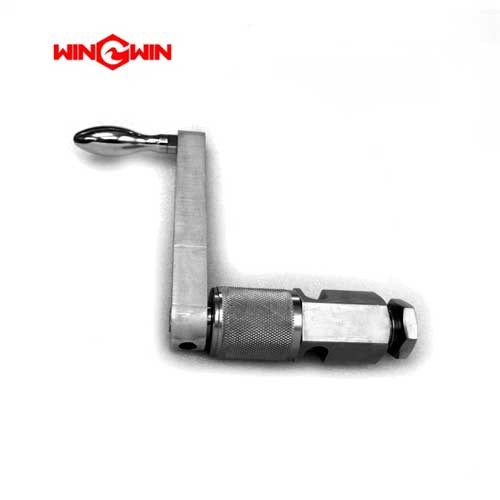
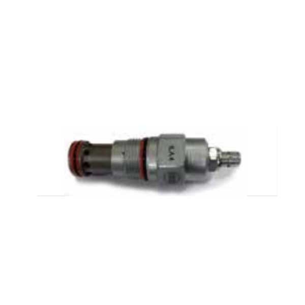
Product Name: Hydraulic Manifold Relief Valve (Adjustable) – Part Nos. 400076-1 & 400076-2
Description:
The Hydraulic Manifold Relief Valve (400076-1 / 400076-2) is a precision pressure control component designed for high-pressure waterjet cutting systems. This adjustable, manifold side-mount relief valve serves as the primary overpressure protection device for the hydraulic circuit in waterjet intensifier pumps . The component monitors hydraulic oil pressure entering the manifold; if the pressure exceeds the preset limit, the valve opens to divert excess fluid, preventing damage to the intensifier assembly, seals, and high-pressure cylinder.
This is a critical safety and system stability component. In KMT Streamline SL-V Plus series systems, the main system relief valve monitors oil pressure entering the manifold. If hydraulic pressure exceeds 3,400–3,407 psi (approximately 234–235 bar), the valve opens to limit the pressure . The relief valve is drain-equipped to prevent oil from collecting behind the valve, ensuring consistent pressure regulation under all operating conditions .
Applications:
Provides system overpressure protection in waterjet intensifier pump hydraulic circuits
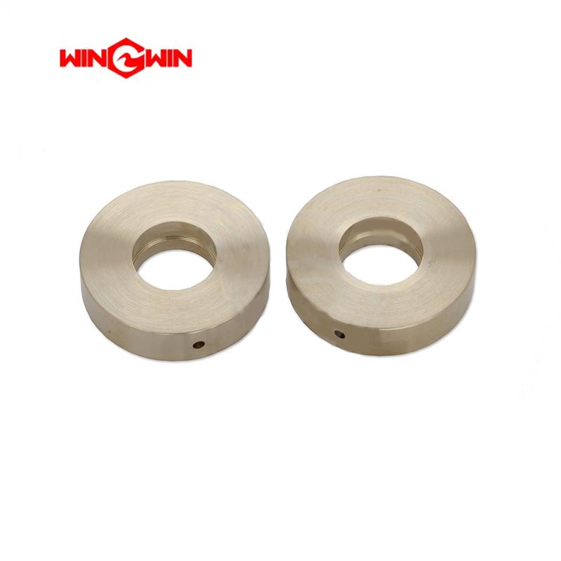
Mounts directly to the hydraulic manifold block
Used during system pressure calibration and setup
Compatible with H2O Jet and KMT waterjet intensifier systems
Features:
Adjustable Design: Allows precise setting of system maximum operating pressure to match specific cutting requirements
Manifold Side Mount: Direct porting to hydraulic manifold for compact integration
Factory Calibrated: While adjustable, the valve should be set according to manufacturer specifications; typical system relief pressure is approximately 3,400 psi (234 bar)
Drain Port: Ensures consistent pressure response by preventing fluid entrapment behind the valve mechanism
Integral Safety Function: Automatically limits system pressure to prevent component damage and operator injury
Maintenance:
When to Replace / Inspect:
Pressure Instability: If the system exhibits fluctuating cutting pressure or the intensifier cycles erratically, the relief valve may be malfunctioning
Overheating: If hydraulic oil temperature rises suddenly or exceeds normal operating levels, the relief valve may be cracking open prematurely, allowing excessive oil to bypass and generate heat
Inability to Build Pressure: If the intensifier cannot achieve rated cutting pressure even though the pump is running, a stuck or leaking relief valve could be diverting flow
Valve Chattering / Unusual Noise: Audible squealing or chattering from the valve indicates potential internal wear or debris in the valve seat
Scheduled Preventive Maintenance: The relief valve should be inspected during major pump overhauls for signs of debris, spring fatigue, or seat wear
Inspection & Replacement Guidelines:
Full Depressurization (Critical): Before any maintenance, fully depressurize both the hydraulic system and the high-pressure water system, shut off the main electrical disconnect, and follow lockout/tagout procedures. Never adjust or remove a relief valve while the system is under pressure.
Factory Calibration Note: In some systems, the relief valve is specified as factory calibrated and not serviceable . In adjustable versions, precise tools and procedures are required for recalibration.
Pressure Setting: Adjust the relief valve to the manufacturer's specified pressure setting (typically 3,400–3,500 psi for 60K systems) using a calibrated pressure gauge on the manifold .
Debris Contamination: If the relief valve sticks or leaks, internal contamination (debris, metal fines, or sludge) is a common cause. Clean hydraulic oil and proper filter maintenance are essential for valve longevity .
Spring and Seat Inspection: During overhaul, inspect the valve spring for fatigue or breakage and inspect the valve seat for pitting or wear. Replace worn components with genuine OEM parts.
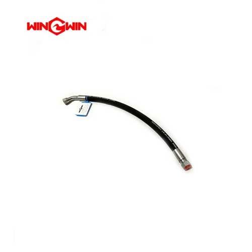
Drain Line Check: Ensure the valve drain line is not kinked or blocked; a blocked drain can affect valve response and sealing .
System Integration: The relief valve works in conjunction with the main hydraulic pump compensator and other pressure control valves to maintain stable system operation .
Oil Temperature Management: Monitor oil temperature to ensure it stays within normal range (typically below 145°F / 63°C); excessive heat can cause the relief valve to function improperly .