301004-2-End-Cap-Assy-15-GPM-60k-Intensifier-Parts
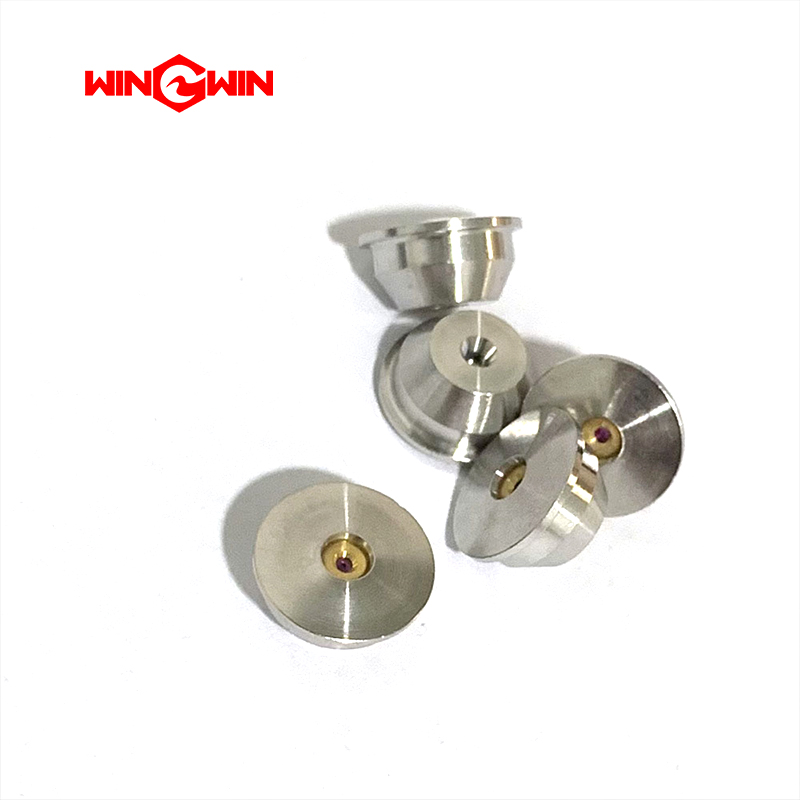
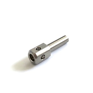
Product Name: End Cap Assembly (15 GPM, 60k) / High Pressure Cylinder End Cap (Part No. 301004-2)
Description:
This component is the End Cap Assembly for the high pressure cylinder, designed for waterjet intensifier pumps rated at 60,000 PSI (approximately 4,137 bar) and 15 GPM . It serves as the terminal closure for the high pressure cylinder, sealing the ultra-high pressure chamber and providing the mounting interface for the check valve assembly .
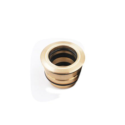
The end cap is a precision-machined structural component, typically constructed from high-strength stainless steel or hardened alloy. It is engineered to withstand extreme internal pressures and cyclic loading while maintaining a leak-proof seal. Critical features include precision-machined threads for engagement with the high pressure cylinder, a 45-degree cone sealing surface that creates a metal-to-metal seal with the sealing head, and internal O-ring grooves for static sealing . The end cap also integrates the inlet water groove and provides the mounting location for the discharge high pressure check valve. Proper torque during installation is essential, with hand-tightening recommended to avoid over-compression .
Applications:
Seals the high pressure end of the intensifier cylinder in 60,000 PSI waterjet pumps
Provides structural mounting for the check valve assembly within the end cap body
Houses the interface between the high pressure cylinder and the sealing head
Suitable for 15 GPM, 60k-rated waterjet intensifier systems
Features:
High-Strength Stainless Steel Construction: Manufactured from corrosion-resistant material to withstand extreme pressure cycling
45-Degree Cone Sealing Surface: Precision-machined surface creates metal-to-metal seal with the sealing head for leak-proof high pressure containment
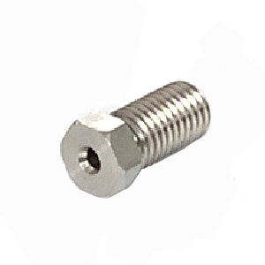
Integrated Check Valve Mounting: Accommodates the discharge high pressure check valve within the end cap body
Precision-Machined Threads: Ensures secure engagement with the high pressure cylinder
O-Ring Grooves: Machined internal grooves for static sealing O-rings
Semi-Wear Component: Classified as a "semi-wear part"; requires periodic inspection for thread wear, sealing surface damage, deformation, or cracking
Maintenance:
Inspection Criteria:
Visual Inspection: Regularly inspect the end cap for cracks, corrosion, thread galling, sealing surface scoring, or deformation
Sealing Surface Check: Examine the cone seal surface for nicks, scratches, pitting, or erosion marks
Thread Inspection: Check the high pressure cylinder mating threads for wear, galling, or damage
O-Ring Groove Condition: Inspect internal O-ring grooves for burrs or damage that could compromise static sealing
Replacement Indicator: Replace the end cap immediately if the cone sealing surface is damaged or if cracks, severe thread wear, or deformation is detected
Removal and Installation Procedures:
Full Depressurization (Critical): Before any maintenance, fully depressurize the waterjet system, place the main electrical disconnect in the OFF position, bleed down all high pressure lines, and observe lockout/tagout safety rules
Disassembly: Use a pin spanner wrench to turn the end cap counter-clockwise; tapping the wrench with a plastic mallet may be required to break the end cap loose. It is recommended to remove the check valve assembly simultaneously
Check Valve Service: If only the check valves are being serviced, the intensifier does not have to be removed from the cabinet; however, the area must be free of airborne dust and particles
Reassembly Preparation: Apply anti-seize compound to the flat end of the high pressure cylinder and to the shoulders of the check valve before reassembly
Installation: Position the sealing head with the white plastic spacer ring installed on the "nose", then place the end cap over the sealing head and thread it clockwise onto the cylinder until it bottoms out
Torque Compliance: Tighten the end cap with a spanner wrench using only hand force; finish with a single, light tap on the wrench handle. Any torque greater than this could cause difficulties during future servicing
Post-Installation Check: After reattaching high and low pressure piping, start the pump at low pressure (without a cutting orifice) to flush high pressure passages, then operate at high pressure with orifice installed to check for leaks
Diagnostic Indicators (Service When Observed):
High pressure water temperature at the outlet fitting exceeding 49°C (120°F) indicates excessive back-flow through the outlet check valve
Hydraulic piston slamming to the end of travel indicates excessive back-flow through the inlet check valve
Repetitive spiking of high pressure water pressure indicates one or both check valves may be leaking excessively