301011-4-Electric-Shift-Sensor-Assy-15-GPM-60K-Intensifier-Parts
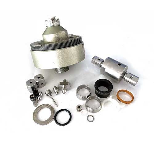
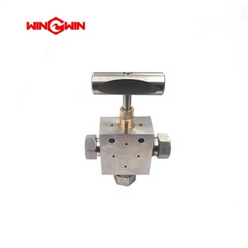
Product Name: Electric Shift Sensor Assembly / Proximity Switch Assembly (15 GPM, 60K) – Part No. 301011-4
Description:
This component is an electric shift sensor assembly, also known as a proximity switch assembly, specifically designed for 60,000 PSI (approximately 4,137 bar), 15 GPM waterjet intensifier pumps. It is a critical control component that monitors the position of the reciprocating hydraulic piston within the intensifier cylinder and sends electrical signals to the pump's control system to initiate the reversal of the piston stroke.
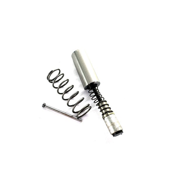
The assembly is a direct OEM replacement part, manufactured to original equipment specifications, and is designed for drop-in compatibility with specific intensifier models. It includes the sensor element, mounting hardware, and an electrical connector for integration with the machine's control system. The sensor is magnetically activated by the presence of the metallic surface of the hydraulic piston as it approaches the end of its travel.
This sensor assembly is essential for generating the continuous, rapid-cycle operation required to produce constant ultra-high-pressure water flow for precision cutting. When the piston nears the end of its stroke, the sensor detects the piston's proximity and sends a signal to the directional control valve (pilot valve), which reverses the flow of hydraulic fluid, causing the piston to change direction.
Applications:
Controls the directional shifting of the hydraulic piston in 60,000 PSI, 15 GPM waterjet intensifier pumps
Sends end-of-stroke position signals to the machine's PLC or integrated shift module for precise pump cycling
Ensures stable, continuous ultra-high-pressure water output for cutting operations
Compatible with 15 GPM, 60k-rated waterjet intensifier systems
Features:
Precise Position Detection: Magnetically activated by the metallic surface of the hydraulic piston to determine stroke completion
Visual Status Indicator: Built-in LED indicator; green light indicates power to the switch, red light indicates activation when the piston is detected
Integrated Assembly: Includes sensor element, mounting hardware, and electrical connections in one unit
OEM Replacement: Manufactured to original equipment specifications for drop-in compatibility
Rapid Switching: Enables fast, consistent reversal of the intensifier piston for smooth pressure delivery
Compatibility: Fits 15 GPM, 60,000 PSI waterjet intensifier systems from multiple manufacturers
Maintenance:
Function Testing:
Periodically verify that the sensor activates correctly by observing the indicator light change from green to red as the piston strokes
The green light indicates there is power to the switch; the light turns red when the switch is activated
Failure Diagnosis:
Stalled or Erratically Shifting Intensifier: The most common shift sensor problems include a stalled or erratically shifting intensifier caused by a broken spring, or a stalled intensifier caused by a break in the wiring
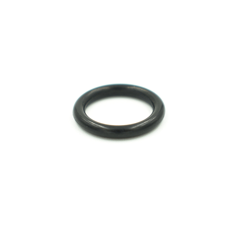
Leakage: Worn O-rings can cause leakage around the sensor assembly
Pump Fails to Reverse: If the pump fails to reverse direction or pressure output becomes erratic, test the sensor signal
Electrical Issues: Check the Hall sensor, related relays, and the electrical circuit including connections
Position Adjustment: If the sensor is not detecting correctly, adjust the position of the sensor switch
Inspection and Replacement:
Visual Inspection: Check the sensor, wiring harness, and connector for signs of physical damage, wear, or corrosion during routine pump overhauls
Cleaning: Keep the sensor face clean and free from metallic debris or hydraulic fluid residue that could affect sensing accuracy
Replacement Criteria: Replace the assembly if the sensor fails to detect the piston, the LED is unresponsive, the harness is damaged, or the sensor is faulty
Reinstallation Note:
After servicing the intensifier, always ensure the proximity switches are reinstalled and tightened. Failure to do so will result in considerable spraying of hydraulic oil during operation
Full Depressurization (Critical):
Before any maintenance, place the main electrical disconnect in the OFF position, bleed down all high-pressure lines, and follow lockout/tagout procedures. Severe injury can result from high-pressure fluid release if the machine is not properly locked out
Cross-Reference Information:
Direct replacement for waterjet intensifier systems with electric shift control; not compatible with mechanical shift valve systems