606050-5-Hydraulic-Oil-Pressure-Guage-606050-6
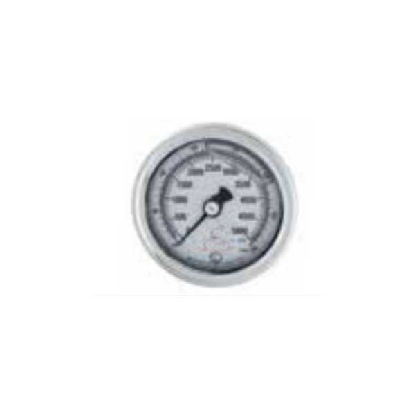
Product Name: Hydraulic Oil Pressure Gauge – Part Nos. 606050-5, 606050-6
Description:
This component is a hydraulic oil pressure gauge, an analog dial-type instrument specifically designed for the hydraulic power unit of waterjet cutting systems. It is used to measure and display the pressure of the hydraulic fluid that drives the intensifier pump.
This gauge is a critical diagnostic tool for maintaining and troubleshooting the machine. By monitoring the hydraulic pressure, the operator can verify that the pump is building the correct amount of pressure to drive the intensifier. It can quickly reveal problems such as incorrect pump compensator settings, a failing hydraulic pump, or a malfunctioning pressure relief valve .
It is important to distinguish this gauge from the high-pressure water gauge. The "Hydraulic Oil Pressure Gauge" monitors the low-pressure oil circuit (typically 300–3,500 PSI / 20–240 bar), while the high-pressure water gauge monitors the output of the intensifier (typically 60,000 PSI / 4,100 bar) .
Applications:
Monitors the hydraulic system pressure of the waterjet intensifier pump.
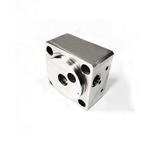
Installed on the hydraulic pump manifold, valve block, or power unit.
Used to set and verify the pump compensator (high-pressure) and differential (low-pressure) settings .
Essential for diagnosing pump failure, pressure loss, and intensifier overstroking issues .
Features:
Analog Dial Display: Provides a simple, at-a-glance reading of system pressure.
Pressure Range: Typically scaled from 0 to 5,000 PSI to cover standard hydraulic system pressures (pump compensator is typically set to ~3,150 PSI, with relief at ~3,700 PSI) .
Glycerine-Filled (Often): A liquid-filled gauge is common to dampen pointer vibration caused by pulsation from the hydraulic pump, ensuring a stable, readable display.
Stainless Steel Case: Corrosion-resistant housing suitable for industrial waterjet environments.
Primary Diagnostic Tool: The needle’s behavior (steady, fluctuating, slow to rise) is the primary indicator of hydraulic pump and valve health .
Maintenance:
When to Replace (Failure Diagnosis):
Zero Offset: When the hydraulic pump is off, the needle must return exactly to the zero stop. If it does not, the internal mechanism is damaged, and the gauge must be replaced.
Fluctuating Needle: A needle that jumps erratically or vibrates excessively (beyond normal dampened pulsation) indicates internal wear or air in the system.
Condensation/Fogging: If the internal window becomes fogged, the gauge seal has failed, and the reading will be inaccurate.
Physical Damage: A cracked lens, dented case, or damaged connection threads require immediate replacement for safety.
Inconsistent Readings: If the pressure reading does not correlate with the machine's performance (e.g., cuts fine but reads low), the gauge is faulty.
Usage & Inspection Guidelines:
Baseline Verification: When the pump is running in high-pressure mode, note the stable "normal" pressure reading (e.g., 3,150 psi). A sudden change from this baseline indicates a problem.
Compensator Adjustment: This gauge is used to set the pump compensator (high-pressure) screw. The compensator is typically factory set to 3,150 psi and is essential for the intensifier to build full cutting pressure .
Differential Adjustment: This gauge is also used to set the differential (low-pressure) screw, which controls the pump's output when the intensifier is not stroking. This is typically set to ~300 psi .
Relief Valve Check: If the gauge shows pressure slowly climbing above the compensator setting, the pressure relief valve may be stuck closed.
Line Inspection: Ensure the small diameter hydraulic line leading to the gauge is not kinked, pinched, or leaking, as this will cause false readings.
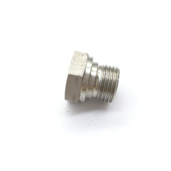
Thread Care: When replacing the gauge, use a wrench on the gauge's fitting hex (not the case) to tighten it. Apply a small amount of thread sealant to the male threads to prevent hydraulic fluid leaks.
Full Depressurization (Critical): Always fully depressurize the hydraulic system, shut off the high-pressure water pump, and follow lockout/tagout procedures before removing or installing a hydraulic pressure gauge.