
100011-3-Plunger-Retainer-15-GPM-60k
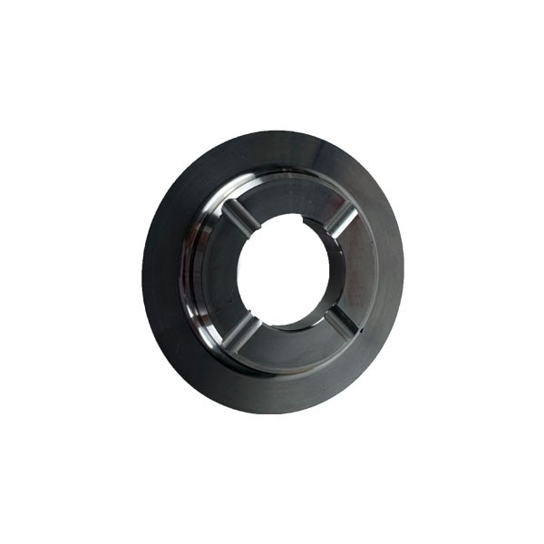
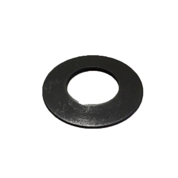
Product Name: Plunger Retainer / Plunger Retainer Assembly, 15 GPM, 60k (Part No. 100011-3)
Description:
The Plunger Retainer 100011-3 is a precision-engineered mechanical component specifically designed for the piston assembly of 60,000 PSI (approximately 4,137 bar), 15 GPM waterjet intensifier pumps . This component works in conjunction with the plunger button socket, O-rings, backup rings, and retainer pins to securely attach the ceramic plunger to the hydraulic piston . The retainer mechanism ensures stable, vibration-resistant mechanical connection that maintains proper alignment and prevents loosening under the extreme cyclic forces of ultra-high-pressure operation.
The plunger retainer is critical for maintaining the integrity of the high-pressure water generation process. When the plunger is inserted into the piston's button socket, the retainer pins extend to grip the plunger button, creating a secure snap-in attachment . The design includes provisions for inspection of pin holes, seal grooves, and socket wear to ensure continued reliable operation.
Applications:
Secures the ceramic plunger to the hydraulic piston within the intensifier pump assembly
Part of the plunger retention system in 60,000 PSI, 15 GPM waterjet intensifier pumps
Essential for maintaining proper plunger alignment during reciprocating motion
Used during major pump overhaul and preventive maintenance procedures
Features:
Precision Engineered: Manufactured to exacting tolerances for secure fitment within the plunger button socket
High-Strength Construction: Designed to withstand the high contact forces between the piston and plunger during operation
Integrated Retention System: Works with flat snap rings and retainer pins to lock the plunger in place
60,000 PSI & 15 GPM Rating: Engineered for continuous operation at ultra-high pressure with medium flow capacity
OEM Compatibility: Direct replacement part for 60k-rated intensifier systems
Maintenance:
Visual Examination: Inspect the plunger retainer and associated components for unusual wear, scoring, deformation, or damage
Pin Hole Inspection: Clean and inspect the pin holes for unusual wear, deformation, or hole enlargement. Ensure pins move freely without excess side play
Seal Groove Inspection: Clean and inspect the seal grooves for residue buildup or surface marks that could cause seal leaks
Socket Wear Inspection: Inspect the plunger button sockets for unusual wear; note that due to high contact force, the plunger may make an impression in the bottom of the socket
Always Use New Seals: Apply manufacturer-recommended high-pressure grease to new plunger button backup rings and O-rings. Install them in the internal groove of the plunger socket
Critical Backup Ring: Ensure backup rings are installed - if the backup ring is not installed, the plunger can be forced out of the plunger socket during operation
Retainer Pin Verification: After installing retainer pins, verify that each pin moves freely without excess side play in the pin holes. Install flat snap rings over the pins
Snap-In Feature Check: Use a plunger removal tool to ensure the pins retract to release the plunger and close to retain the plunger in a uniform manner
Pin Engagement Verification: Use a flashlight to verify that all six pins are equally extended to grip the plunger button
Flush Installation: Ensure the plunger is flush to the socket; look for gaps. The plunger should be fully seated
Surface Condition Monitoring :
Monitor plunger surfaces for longitudinal scratches, flaws, discoloration, or dull appearance. If these conditions become severe, the high-pressure seal assembly and possibly the hydraulic cartridge seal will leak
Accumulation of debris on component surfaces can be removed by polishing in a radial direction with 600-grit sandpaper
Severe surface flaws typically cannot be repaired on site; components may need replacement or factory reconditioning
Safety Precautions:
Full Depressurization: Always fully depressurize the waterjet system and follow lockout/tagout procedures before removing or servicing the plunger retainer and associated components
Product recommendation
-
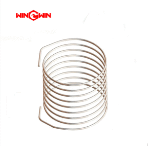
Waterjet robot Parts Coil 103262 Coil Axis 4 5 6 top ABB M98 2400 10
-
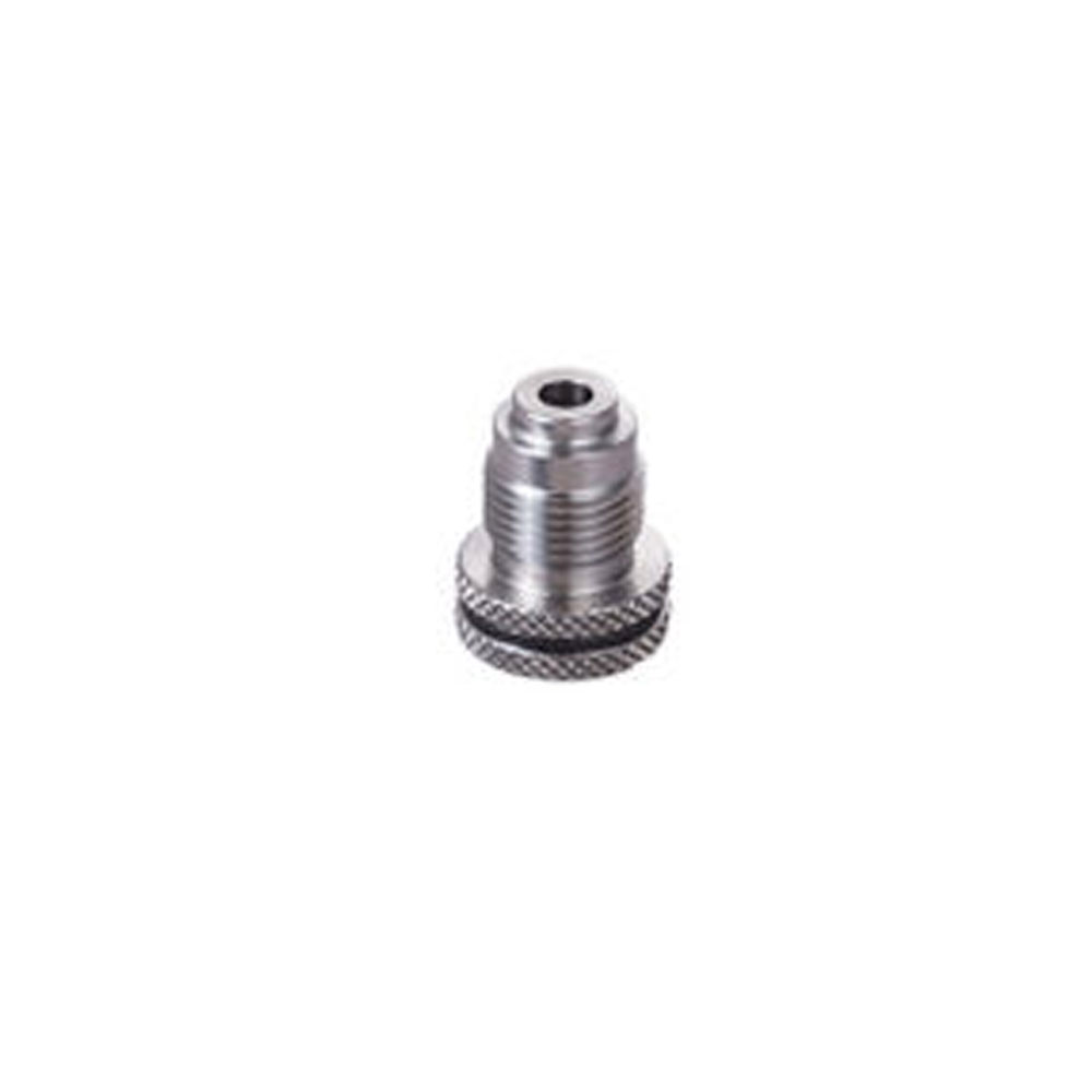
20470417 seal installation tool
-
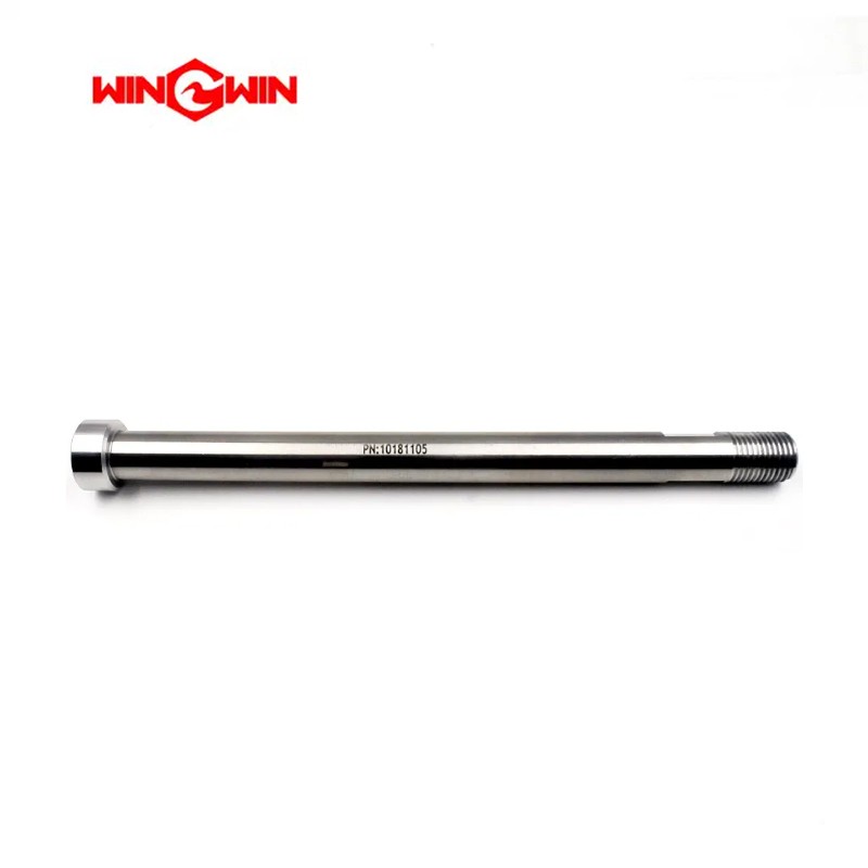
10181105 Actual in 9.65 (245.11) Nominal in 10.00 (254.0)
-
315163080255-cup-ring-BHDT-spare-parts
-
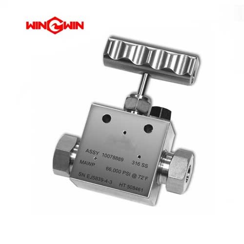
10078889 High Pressure Fitting and Valve Assemblies 2 Way Straight, .56
-
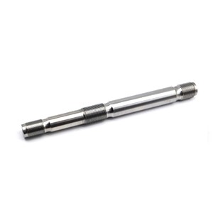
014589-1 High-pressure Tie Rod
-
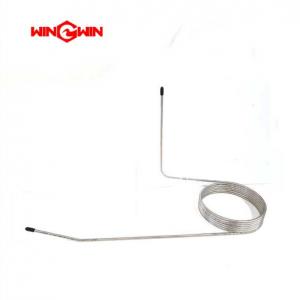
Robotic Waterjet Coils 105838 Axis 2 IRB2600
